HOW IT WORKS
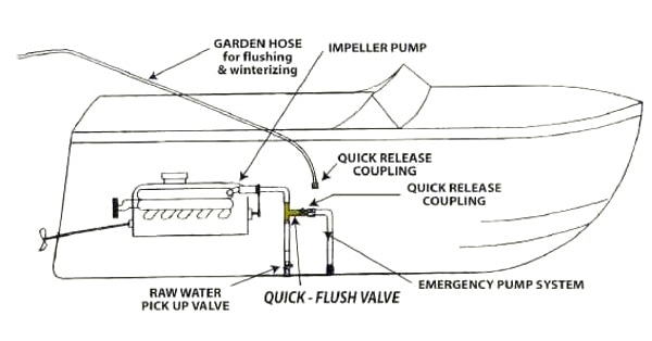
With the Quick Flush Valve, permanently installed between the hose leading from the raw water pickup, to the engine's impeller pump, you are ready to:
- flush your engine
- winterize your engine
- use the system as an emergency bilge pump
- flush your engine
- winterize your engine
- use the system as an emergency bilge pump
INSTALLATION
|
Inboard Marine Engine
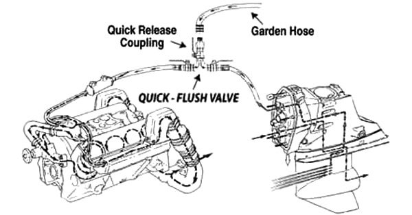
If you have an engine with a cooling water inlet thru-hull, the hose from the thru hull is cut and the Quick Flush Valve is inserted in the line and hose clamped.
|
I/O Marine Engine
If you have an I/O engine, locate the cooling water line from the outdrive to the engine and insert the Quick Flush Valve in that line. Tighten hose clamps and you are done.
|
NORMAL OPERATION
Description
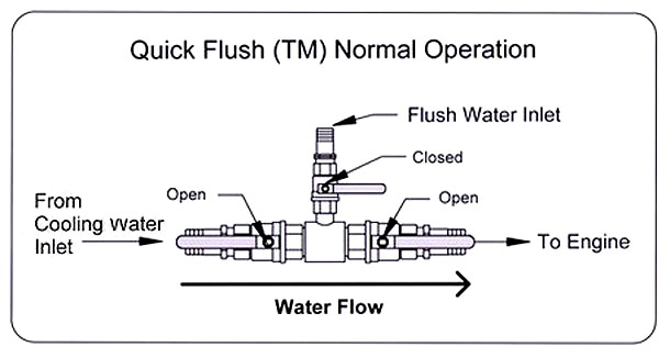
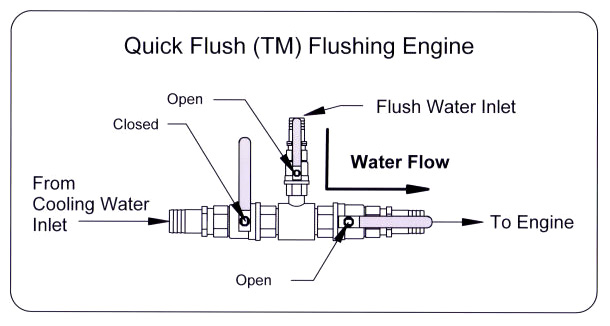
Plumb the Quick Flush Valve permanently into your engine's cooling system. In normal operation the two main valves are open, allowing cooling water to flow from the raw water pickup to the engine, while the flush water inlet valve is closed. This maintains the flow of cooling water to the engine during normal operation. The large valve size eliminates any possibility of a restriction in the cooling flow.
Scheme
Animations
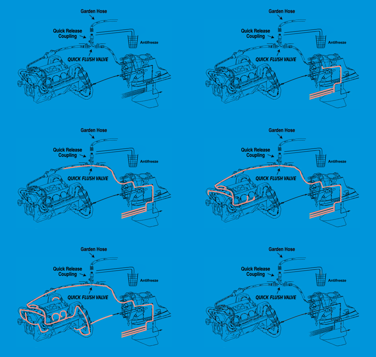
FLUSHING
Description
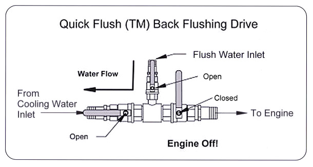
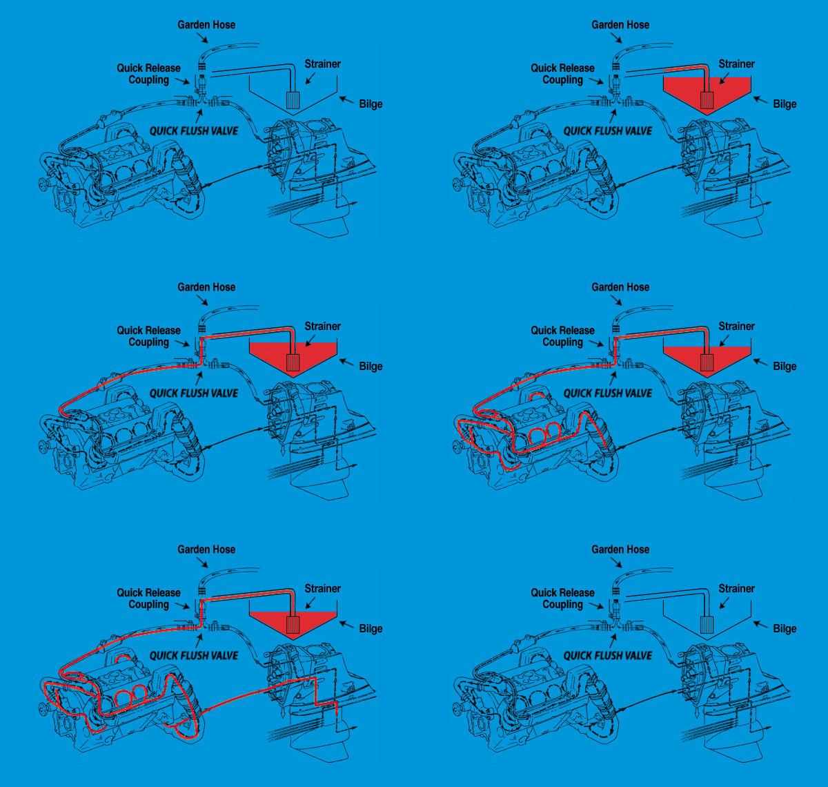
Attach an ordinary garden hose to the Quick Flush Valve, turn raw water pickup valve to the closed position and open the flush valve handle. Turn on the garden hose, start engine and let run for a few minutes. When finished, reverse the above procedures ensuring you turn raw water pick up valve back to the open position.
Schemes
Animations
WINTERIZING
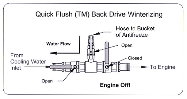
Description
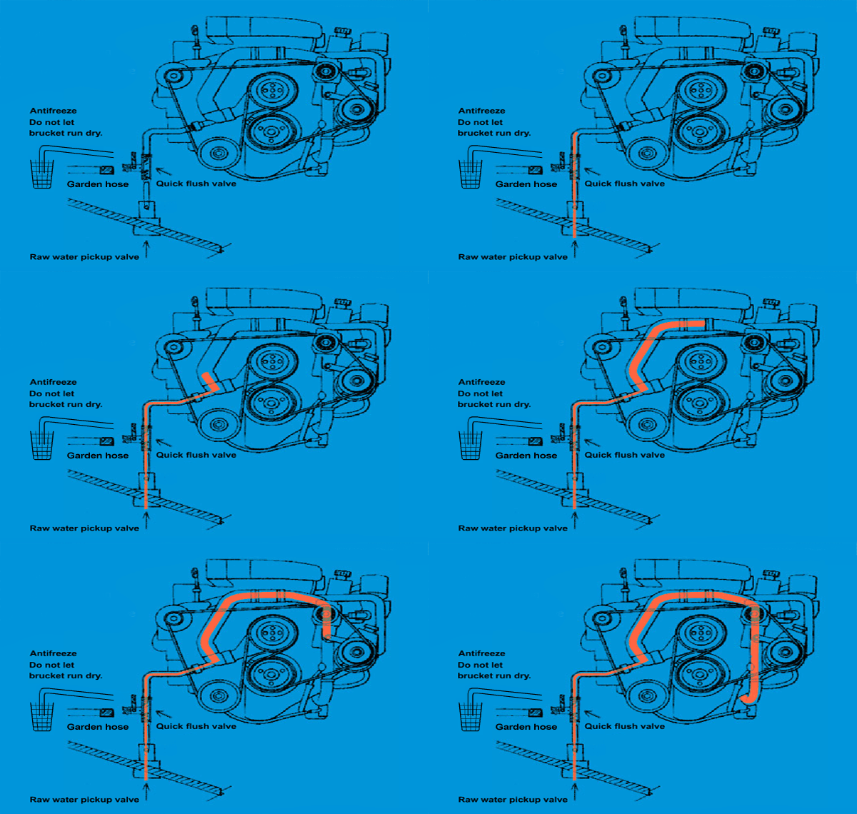
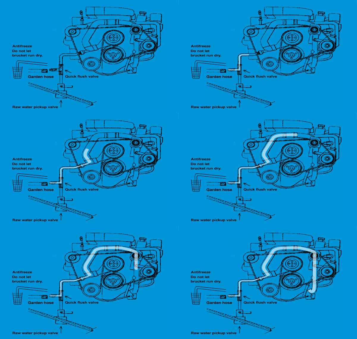
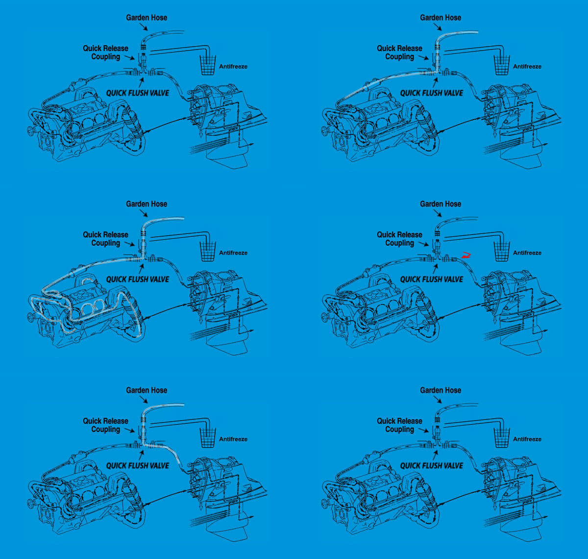
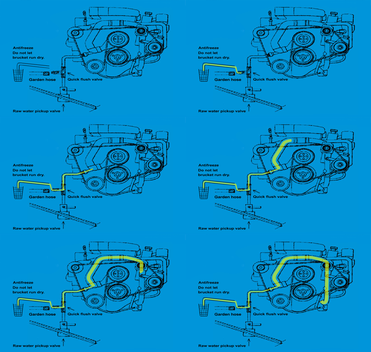
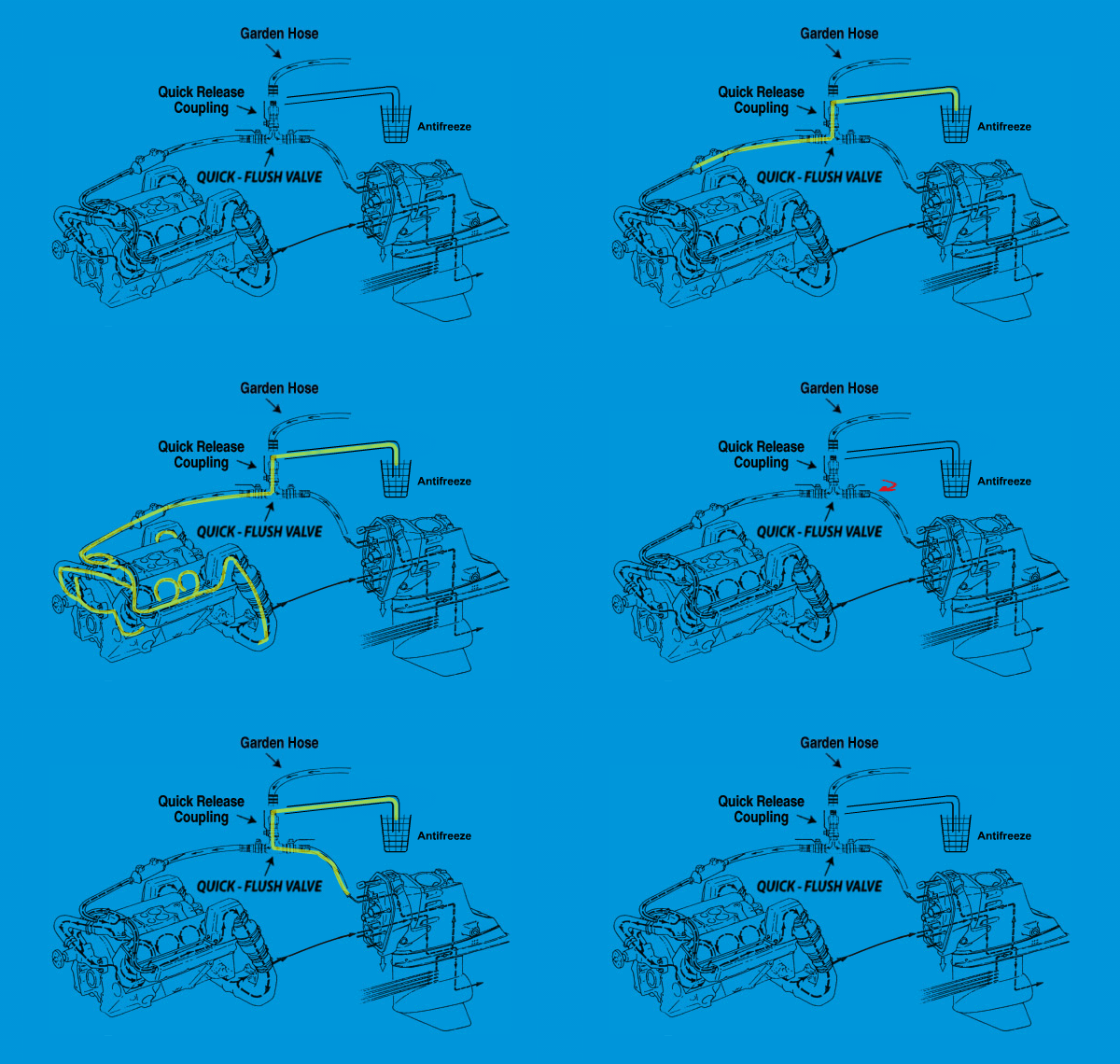
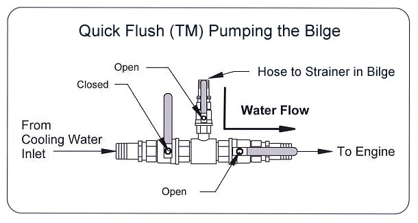
Connect the optional Flush and Winterizing Hose Kit to the Quick Flush Valve. Insert the strainer end into a bucket of water/ antifreeze mixture ensuring that there is enough volume of mixture for boats engine size. Close raw water valve, open Quick Flush Valve handle and start engine. When you see water/ antifreeze mixture coming out of engine discharge, shut engine down.
DO NOT LET BUCKET RUN DRY!
DO NOT LET BUCKET RUN DRY!
SchemES
Animations
EMERGENCY BILGE PUMP
Description
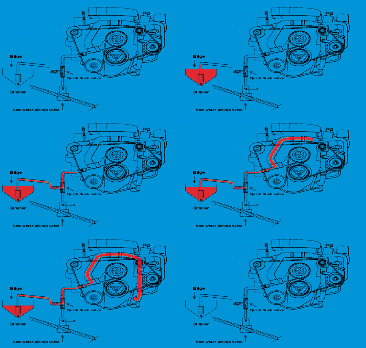
Using the winterizing configuration, the hose kit can also be used as an emergency bilge pump, by laying the strainer into the lowest point of the bilge and using your engine as the pump.
scHEME
ANIMATIONS
SIZES
GASOLINE ENGINES, GENERATORS, A/C UNITS
5/8" | 3/4" | 1" | 1 1/4"
DIESEL ENGINES
1" | 1 1/4" | 2"
I/O ENGINES
3/4" | 1 1/4"
MANUAL
| ||||||||
NOTES
NOTE 1:
Quick Flush Valve Systems are constructed with rugged and durable bronze fittings that will last for years, unlike others that use fatigue-prone plastics.
NOTE 2:
Whether you trailer or dock, follow your prescribed engine maintenance, and keep your motors sweet and clean with regular flushing.
NOTE 3:
Valve must be grounded to prevent galvanic corrosion.
INSTALLATION NOTE 1:
Quick Flush Valve Systems are sized to fit the Cooling Hose Inner Diameter (ID) of the Engine water supply.
INSTALLATION NOTE 2:
Components (valves and tees) of the Quick Flush Valve Systems are sized for proper cooling water flow and are not the same as the hose ID.
INSTALLATION NOTE 3:
Valve is loosely assembled, insure all connections are tight after determining handle orientation and before final installation.

